
Dull Bit Grading System
Significance and historical perspective of dull bit grading system:
All drilling bits have a life. If a bit reaches a point where it’s not able to drill ahead efficiently in a cost-effective manner, it is pulled out of the hole to be replaced with another bit.
Once out of the hole, the bit is carefully analyzed to understand the areas and types of wear. The dull bit condition indicates the difficulty the drill bit faced while drilling on the bottom. Dull bit grading can indicate weak areas of the tool or even poor operating practices.
A good understanding of how to grade and analyze dull bits can lead to better bit selection and use, eventually cutting overall drilling costs. A critical evaluation of the pulled bit provides vital clues not only for the selection of a bit for the next run but also for redesigning the bit to overcome its weaknesses for future drilling under similar conditions. Hence it is critical to grade bits accurately and consistently to be able to achieve optimized cost-effective drilling performance.
The first dull bit grading guidelines were established by the ‘American Association of Drilling Contractors (AAODC)’ in the year 1961. It was primarily a system of grading the conditions of tooth, bearing, and gauge of a roller cone bit. Hence it was also known as the ‘TBG’ system. In 1987, the ‘International Association of Drilling Contractors (IADC)’ came up with a more elaborate system of grading used bits. Most companies adopted the IADC system, which was refined with changes from time to time and is still a prevalent system of grading the condition of pulled-out bits.
Grading of Bits:
The IADC grading system applies to all types of tri-cone roller bits whether they have steel teeth or tungsten carbide insert cutters or fixed blades. Grading of bits typically uses the 8-column system shown below:

The first 4 columns grade the conditions of cutting structures.
The 5th column grades the condition of bearing.
The 6th one measures the gauge of the bit.
The 7th column is for any other dull characterization identified in the bit.
The last column defines the reason for pulling out the bit.
Steps for grading a bit:
1. Cutter Wear Grading:
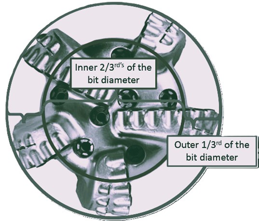
Inner teeth are typically defined as the ones that do not touch the wall of the drilled hole. Whereas the outer teeth are the ones that do touch the wall.
The first step should be to identify the regions where cutters will be termed as inner and outer. A 1/3rd – 2/3rd rule is used for this identification as indicated in the picture below.
The condition of Inner and outer cutters is measured in a linear scale of 0-8, where 8 means that no usable cutters are left and 0 means that there is no wear. So, a 4 will indicate 50% wear on cutters.
The best way to establish what would be a 4 is to visualize an imaginary line at half of the cutter. If the cutter is damaged to that line, it would be a 4. If the wear is half of that 50% line, it will be a 25% line and that will be a 2. Wear only to half the 25% line will be a 1. If there is no wear, the cutter should be marked a 0.
Since there are several cutters in the inner and outer areas of a cone, the average wear of all the cutters is calculated.
For example, if the wear on inner and outer row cutters on one blade is estimated as below:
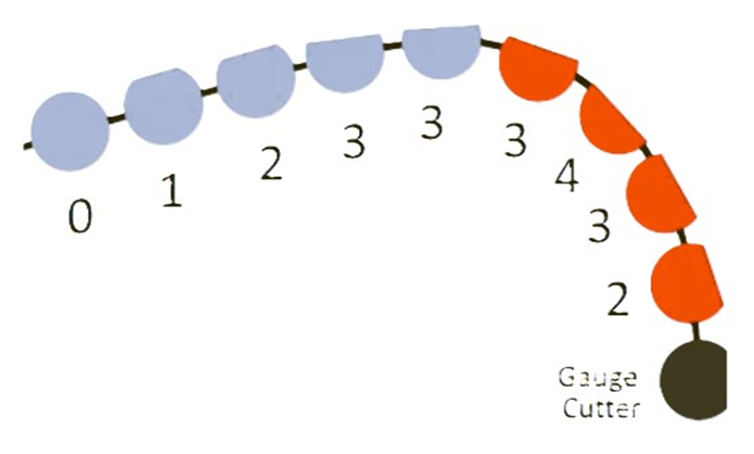
Inner Row: Cutter 1 = 0, cutter 2 = 1, cutter 3 = 2, cutter 4 = 3, Cutter 5 = 3, then the average dull condition for the inner cutting structure will be 0+1+2+3+3 = 9/5 = 1.8 ~ 2
The grading for the outer areas is also averaged in the same way, the gauge cutters are not included. Cutter 1 = 3, cutter 2 = 4, cutter 3 = 3, cutter 4 = 2. The average wear for the outer cutting structure will be 3+4+3+2 = 12/4 = 3
2. Dull Characteristics:
The 3rd column indicates the ‘Dull Characteristic’ of the cutter. If no dull characteristic is seen on the cutter, ‘NO’ should be indicated. If multiple characteristics are seen, the one that hampered the progress should be indicated. The second most notable condition of cutter and bit is indicated in the 7th column as ‘Other Dull Characteristic’. Standard codes are listed below:
BT Broken Teeth/Cutters
LT Lost Teeth/Cutters
HC Heat Checking
RG Rounded Gauge
CT Chipped Teeth/Cutters
SS Self Sharpening Wear
WT Worn Teeth/Cutters
WO Washed Out – Bit
BU Balled Up
PN Plugged Nozzle/Flow Passage
SD Shirttail Damage
TR Tracking
LN Lost Nozzle
BC Broken Cone
LC Lost Cone
RO Ring Out
CC Cracked Cone
CD Cone Dragged
CI Cone Interference
CR Cored
OC Off-Center Wear
JD Junk Damage
ER Erosion
NO No Major/Other Dull Character
3. Location of Wear:
The 4th column in the grading chart firms up the location of the dull characteristic mentioned in the chart. Standard codes, along with the number of the cone, are used for indicating the location of the damage for roller cone bits.
G – Gauge: The gauge row that touches the hole wall
N – Nose: The Nose row is the centermost cutting element of the bit
M - Middle Row: Cutting elements between nose and gauge rows
A - All Areas: If the damage is seen on all rows
The cone that has the centermost cutting element is called Cone#1. Other cones are marked as Cone#2 and Cone#3 clockwise, looking down the cutting structure.
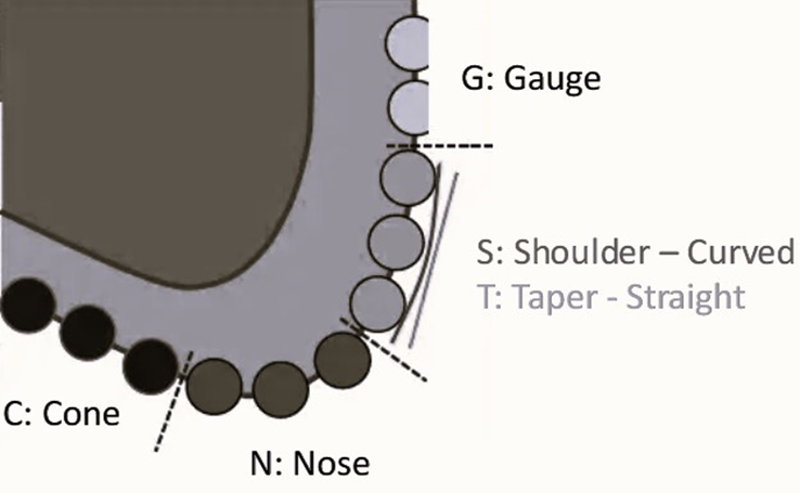
For fixed cutter bits, the following codes are used to define the damage location.
C – Cone N – Nose G – Gauge
T – Taper S – Shoulder A – All
The ‘Shoulder’ defines the rounded profile commonly used in PDC bit. A Straight profile called ‘Taper’ is not commonly used in PDC bits.

4. Bearing Wear:
The bearing wear is only indicated for roller cone bits. For fixed cutter bits, this column is marked as ‘X’. This column assesses the bearing life left on a roller cone bit.
Bearings of a roller cone bit could be either sealed or non-sealed. Non-sealed bearings do not have any mechanism to stop the entry of drilling fluid into the bearing area. The bearings usually are filled with highly viscous grease. For non-sealed bearing roller cone bits, a linear scale from 0 - 8 is used to indicate the amount of bearing life that has been used. Zero indicates that no bearing life has been used, just like a new bearing. Whereas an 8 will indicate that the full life of the bearing has been used. The cone could either be locked or on the verge of being lost.
Sealed bearings have a seal to prevent drilling fluid from entering the bearing area. Light oil can lubricate bearings effectively. However, if the seal fails and allows drilling fluid to enter, the bearings will quickly fail. Hence, a letter code indicates the condition of the seal.
‘E’ indicates an effective seal
‘F’ indicates a failed seal.
5. Gauge Wear:
The 6th column in the IADC dull bit grading chart indicates the wear on the body of the bit. If there is no wear, it is marked as ‘IN’ to indicate that the bit is ‘in-gauge.’ A gauge ring measures the gauge wear, and the under-gauge conditions are indicated in 1/16th of an inch.
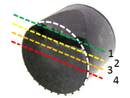
The 2/3rd rule is used to measure gauge wear for roller cone bits. The gauge ring is placed such that it contacts two of the cones at their outermost points. Then, the gauge ring is pulled towards the third cone. The distance between the third cone's outermost point and the gauge ring's inside is multiplied by 2/3 and then rounded to the nearest 1/16th of an inch to indicate the gauge reduction.
The ring is placed over the largest diameter cutter or gauge pad for PDC bits. It is then tightly pulled, and the measured distance is indicated to the nearest 1/16th of an inch.
6. Reason for pulling out the bit:
The 8th column in the grading chart captures the reason for pulling the bit out of the hole. It provides a clue as to whether the bit was pulled due to something wrong with it or was pulled prematurely due to other considerations. This is also indicated as standardized code indicated below:
BHA - Change Bottomhole Assembly
FM - Formation Change
DMF - Downhole Motor Failure
HP - Hole Problems
DSF – Drill string Fatigue
HR - Hours
DST - Drill Stem Failure
PP - Pump Pressure
DTF - Downhole Tool Failure
PR - Penetration Rate
LOG - Run Logs
TD - Total Depth/CSG. Depth
RIG - Rig Repair
TQ - Torque
CM - Condition Mud
TW - Twist-Off
CP - Core Point
WC - Weather Conditions
DP - Drill Plug
WO - Washout-Drill string
Tools for effective grading of a pulled-out bit:
Many articles have described new systems for reporting dull bit conditions, but most drill site workers find it difficult to identify the exact pattern of bit wear. Since dull bit grading is highly subjective, different people grade the same bit differently. New technologies have been developed to help measure and assess bit wear.