
Key attributes and selection criteria of a stabilizer
Stabilizer specifications and standards are defined by API 7-1. Key attributes of a stabilizer are indicated in the figure below:
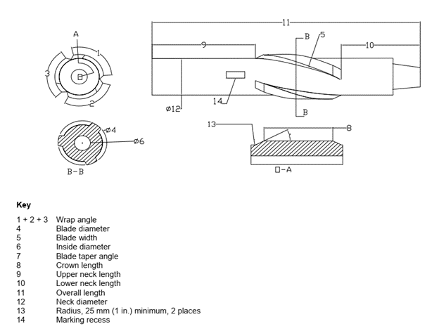
A. Wrap Angle: Wrap angle is measured in degrees and is defined as the total contact that all the stabilizer blades make with the borehole wall. Based on the stabilizer design and drilling operations requirements, the wrap angle can vary from 180 to 600 degrees. Wrap angle does not apply to straight-blade stabilizers. Based on the wrap angle, stabilizers can be defined as
Open spiral: 180 – 220° wrap angle
Full spiral: 300 – 350° wrap angle
Tight Spiral: 500 – 600° wrap angle
Straight blade stabilizers are preferred on bearing housing and motor stabilizers, and help slide. The wrap angle provides stiffness and stability to the drill string. It results in efficient drilling by reducing vibrations and allows an efficient weight transfer to the bit. It is a crucial consideration for spiral blade stabilizer selection, as excessive wrap angle could also have adverse effects.
While drilling, efficient fluid flow and cuttings transportation are essential. Excessive wrap angle can restrict the flow and interfere with the smooth movement of cuttings, which could lead to the balling up of the stabilizer.
The rotation of the drill string creates constant contact between the stabilizer blade and the borehole walls. A high wrap angle increases the contact area, and excessive contact area can lead to higher torque and vibrations that could damage the drill string components. The wrap angle is vital to provide stabilization to the drill string. However, excessive wrap angle could reduce string stability due to excessive vibrations, compromising hole quality and directional control.
More than the optimum wrap angle creates greater force, and the scraping action of the stabilizer could damage the borehole walls.
Hence, carefully considering the wrap angle while selecting a stabilizer is essential. A wrap angle between 270° and 360° is preferred for spiral blade stabilizers. Within this range of wrap angles, the stabilizer offers the optimal combination of BHA stability, low downhole vibration, cutting transport efficiency, and minimal borehole damage.
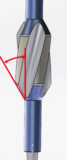
An easy way to visually verify is:
The blades are angled with a right-hand wrap.
The blades are arranged in a manner that there is a clear line of sight between the leading top edge of a blade and the trailing bottom edge of the next blade, as shown in the figure below.

B. Blade Taper Angle: The gauge diameter of a stabilizer blade is more than the mandrel or the main body of the stabilizer. A taper is provided from the main stabilizer body to the blade pad. The taper angle is defined as the angle of the taper to the main body of the stabilizer. The taper angle serves the purpose of a transition from the body of a stabilizer to the blade of the stabilizer.
Having a smooth transition is a crucial design consideration for a drilling stabilizer. An abrupt transition would result in a shoulder that would make the stabilizer hang up while tripping or drilling. It will increase the amount of shock and vibrations, which could lead to potential damage to the drill string and the borehole.
A taper angle ≥ 45° should not be used as it will result in an abrupt transition to the blade. A smooth transition with a taper angle of ≤ 30° is ideal. Anything between 30° and 45° should be carefully reviewed.
C. Bypass Area: The Bypass area of a stabilizer refers to the space between the blades of the stabilizer. A sufficient bypass area is vital to ensure the efficient removal of cuttings. A lower bypass area will result in a sub-optimal flow of cuttings, which will tend to ball up the stabilizer.
The ‘Bypass Area’ is expressed as a percentage and is defined as the ratio of the ‘Junk Slot Area’ of the stabilizer to the ‘Hole Area.’ Since the cutting generation volume depends on the hole being drilled, the optimum Bypass area also depends on the hole size. Bypass area ≥ 35% for hole sizes 10-5/8” or more and ≥ 25% for hole sizes below 10-5/8” is ideal for having optimum clearance for efficient cuttings removal. The bypass area of some RSS and MWD tools may not meet these criteria and could constrain the ROP.
D. Pad Pressure: Pad pressure is the pressure exerted by the stabilizer blades on the borehole wall during drilling operations. The two contributing factors to pad pressure are the total side load and the pad area in contact with the borehole wall. The load on pads depends on several factors, as follows:
While drilling a directional well, the vertical component of the weight acts on the pads under gravity.
While drilling a directional well, the bit must occasionally be steered for inclination and azimuthal correction. This steering load is applied to the borehole walls through stabilizer pads.
The hole curvature and the Dog Leg Severity (DLS) also affect the side load.
Pad pressure is expressed in force per unit area and is a ratio of ‘Total Side Load’ and ‘Pad Area for 180° of Contact’. Excessive pad pressure could cause high torque and damage to the borehole walls. This can lead to poor quality of the hole and result in higher vibration levels. A pad pressure ≤ 300 psi is recommended for efficient drilling. If high side loading is estimated based on hole configuration, a review of stabilizer selection with more extended and broader blades could provide a higher pad contact area and help reduce the pad pressure.
Stabilizer Selection Guideline Summary:

Reference:
(1) API SPEC 7-1
(2) Stabilizer Selection Based on Physics and Lessons Learned, Paul E. Pastusek, Paper presented at the IADC/SPE Drilling Conference and Exhibition, Fort Worth, Texas, USA, March 2018, Paper Number: SPE-189649-MS